[ad_1]
Culturing SMCs on a fibronectin-coated flat glass surface leads to the spontaneous emergence of three-dimensional clusters once a sufficiently high cell density is attained (Supplementary Movie 1). The cluster diameter varies over a wide range of ~100 \({{{{{\rm{\mu }}}}}}{{{{{\rm{m}}}}}}\) to ~3 mm. As shown in Fig. 1a and schematized in Fig. 1c, SMCs within clusters exhibit two distinct patterns of organization. Along the peripheral region of the cluster, particularly in the bottom portion21, cells are oriented radially, have elongated nuclei, and express abundant F-actin, smooth muscle actin (SMA), and myosin heavy chain (MHC), consistent with radial force generation associated with the anchoring to the surrounding SMC layer (Supplementary Fig. S1a). On the other hand, SMCs in the inner region of the cluster assume an architecture that resembles a bird nest with nuclei oriented circumferentially and strikingly lower levels of F-actin, SMA and MHC expression as well as low expression levels of the extracellular matrix (ECM) proteins collagen IV and laminin (Supplementary Fig. S1a–c), suggesting minimal force exertion and cell-substrate interaction. Interestingly, the centermost portion of the cluster often contains a zone of lower cell density (Fig. 1a, b, Supplementary Fig. S1d) that spans a portion of the height of the cluster. Live/dead staining revealed that the vast majority of the cells were viable (Supplementary Fig. S2).
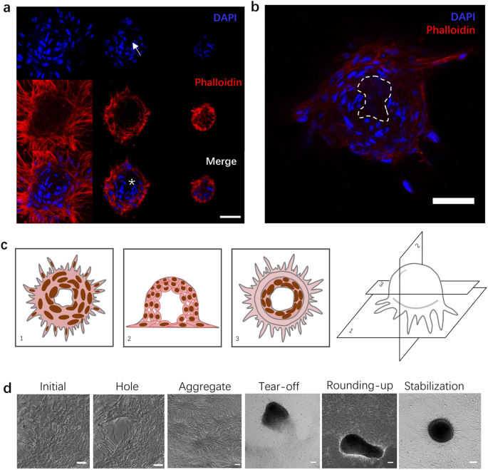
a Confocal images of cellular organization within a cluster. From left to right: z-stack from bottom to top of a cluster for the nucleus (DAPI channel; top row), F-actin (phalloidin channel; middle row), and both channels combined (bottom row). Note the lower cell density zone in the center of the cluster (white arrow on DAPI image; white * on merge image). Scale bar: 50 μm. b A confocal optical section through the midplane of a cluster to more clearly illustrate the lower cell density zone in the center (dashed contour). Scale bar: 50 μm. c Schematic of cellular organization within SMC clusters. d Phase contrast images of the sequence of five distinct events leading to cluster formation. From left to right: initial condition, crack development, aggregate formation, aggregate tear-off, cluster rounding-up from oblong to circular cross-section, and cluster stabilization. Scale bars: 100 μm.
Time-lapse imaging revealed that cluster formation occurs through the following sequence of specific physical events (Fig. 1d): (1) contractility-induced formation of a breach or hole in the flat SMC layer (Supplementary Movie 2), presumably due to an imbalance in the exerted contractile forces as a result of a locally elevated SMC concentration; (2) cellular retraction after hole formation, leading to a bumpy SMC “aggregate” that nevertheless remains fully attached to the substrate over its entire contour (Supplementary Movie 3); (3) additional contraction of the aggregate until a portion of it tears off from the substrate, giving rise to a well-defined three-dimensional cluster (Supplementary Movie 4); (4) rounding-up of the typically oblong cluster into a hemispherical shape (Supplementary Movie 5); and (5) cluster stabilization in its final hemispherical shape until the end of the observation (Supplementary Movie 6). Two clusters that come in contact are sometimes observed to fuse into a single cluster (Supplementary Movie 7). The physics of the different steps outlined above are described next.
Hole development in the SMC layer and aggregate formation
We investigated cluster formation at three different SMC seeding densities: low, medium, and high corresponding respectively to 40,000, 80,000, and 160,000 cells/cm2 (see Methods). For the high-density group, cluster formation initiates within 24 h of seeding with the spontaneous development of holes in the SMC layer (Fig. 2a). In the early stages, the hole may still be partially covered with cells under high strain due to contractile forces from surrounding cells (Fig. 2a).
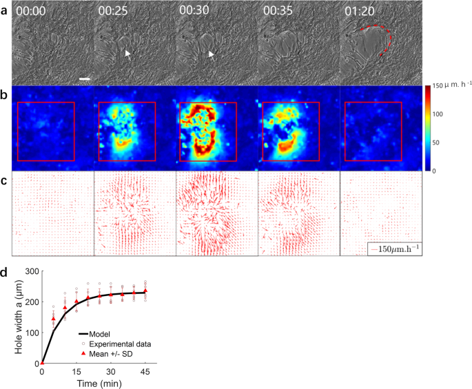
a Phase contrast images of SMCs at different times pre and post-hole development. White arrows denote the position of hole initiation. Fit of the experimental shape of the hole edge by a parabola (red curve) whose equation is indicated in the text. Times are in hours and minutes. Scale bar: 100 μm. b Heat map of SMC tissue speed corresponding to the velocity field shown in (c). c Velocity vector field in the SMC tissue showing the larger velocities in the hole vicinity. d Time evolution of hole width. Comparison between the mathematical model of hole width evolution (solid black curve) to experimental data (brown circles), mean ± SD in red, N = 6). The stretching time (1/C) of hole opening can be observed at the beginning of opening. Interpretation of the constant C is indicated in the text.
We quantified the velocity field in the cell sheet surrounding the hole using particle image velocimetry (PIV) (Fig. 2b, c). The hole widens as cells pull in opposite directions with a progressively increasing velocity. When the cell velocity on either side of the hole attains a peak (typically ~150 μm/h), the cells extending over the hole tear off, which has the effect of releasing the tension and stabilizing the hole width. This is accompanied with an overall reduction in cell velocity below ~20 μm/h.
We also characterized the evolution of the size and shape of the hole (Fig. 2d). This evolution can be modeled as the brittle fracture of a viscoelastic material where the dynamics are dominated by elasticity, similar to the work of Tabuteau et al.23. The profile of the hole is described by the so-called “De Gennes viscoelastic trumpet”24,25, a general result for the fracture of viscoelastic materials. In the region closer to the fracture advancement edge, the profile is a parabola of equation \(y=A\sqrt{x}\), where the symmetry axis y of the parabola is aligned with the direction of hole propagation and the constant \(A \sim \sqrt{\frac{G}{E}}\) depends on the adhesion energy \(G\, \sim {10}^{-2}\) J/m2,23 and the elastic modulus of the SMC cell sheet \(E \sim 2\) kPa. The latter estimate is based on the reported elastic modulus of single SMCs of 10 kPa26 and of experiments with epithelial cells that indicate that the elasticity of a cell sheet is about 5 times smaller than that of a single cell27. Modeling the cell sheet as an elastic sheet, the opening dynamics of the hole width a are driven by elastic recoil and resisted by friction with the substrate. Cell elastic recoil scales as \({Eh}\left({R}_{c}-a\right)\), where h is the SMC layer thickness and Rc is the cell size. Friction scales as \(k{R}_{c}^{2}\frac{{{{{{\rm{d}}}}}}a}{{{{{{\rm{d}}}}}}t}\), where k is the cell-substrate friction coefficient. Balance between these two forces yields a differential equation whose solution is:
$$a={a}_{{{\max }}}\left[1-{{\exp }}\left(-{Ct}\right)\right]$$
(1)
where \(C \sim \frac{{Eh}}{k{R}_{c}^{2}}\) is a constant. By fitting the experimental data (Fig. 2d), we obtain experimentally \({a}_{{{\max }}} \sim 200\,{{{{{\rm{\mu }}}}}}{{{{{\rm{m}}}}}} \sim {R}_{c}\) and \(C \sim 2\times {10}^{-3}\)s−1, which enables us to estimate a cell–substrate friction coefficient of \(k\approx {10}^{9}\) Pa s m-1, similar to the friction coefficient value reported previously28,29. Along its length, the hole opens in successive phases, corresponding approximately to one cell length30 (Fig. 2d). According to our theoretical interpretation, the time to advance one phase should then scale as the stretching time 1/C ~500 s, which is consistent with the observations (5–10 min). This hole development phenomenon is strongly reminiscent of the dewetting of a cell monolayer described by Douezan et al28,31,32., although here the dominant driving force is cell elastic recoil, rather than intercellular adhesion.
The nucleation sites of the holes appear to be related to local fluctuations in cell density (Supplementary Movie 8). These fluctuations, however, need not be very large as we have observed holes forming both in zones where cell density appears to visually be quite uniform as well as in regions where local density variations are more obvious. An established hole represents a valley in the commonly described HV SMC pattern. Once the hole expands, it ultimately forms a ring, leading to a topological transition with the formation of an “aggregate”, a multilayer hill-like structure with a dense central portion and radially outward-pointing cells at the periphery (Supplementary Movie 3 and Supplementary Fig. S3a). These aggregates are highly dynamic as a result of gradients in cell pulling forces. PIV analysis revealed considerably higher cellular velocities in the monolayer (~30 µm/h) opposite to the direction of aggregate movement (Supplementary Fig. S3b, c).
Cluster rounding and stabilization
Driven by cell contraction, aggregates subsequently tear off from the substrate and form independent clusters (Supplementary Fig. S4). These clusters are mobile on the substrate as they progressively round up (Fig. 3a). We analyzed the evolution of cluster size and shape during this rounding-up process as well as cluster motion (Supplementary Fig. S5 and Supplementary Note 1) by imaging the cluster every 20 min (Supplementary Note 2). Cluster morphometric data were obtained through automatic detection of the bright contour in the images (Fig. 3a). Over 24 h, the cluster projected area decreased by about 40% (Fig. 3b) and its circularity (defined as 4πA/P2, where A is the cluster area and P is its perimeter), increased from 0.75 to almost 1 (Fig. 3c), thus indicating that the cluster becomes more compact and round over time. Similar to previous models33, we interpret the dynamics of rounding up as a phenomenon driven by cluster surface tension, arising from both cell contractility and adhesion, and resisted by cluster viscous dissipation. Mathematically,
$$\gamma \dot{S}=-\eta {\int }_{V}\overrightarrow{\nabla }\overrightarrow{u}:\overrightarrow{\nabla }\overrightarrow{u}{{{{{\rm{d}}}}}}V$$
(2)
where γ is the surface tension coefficient, η the cluster viscosity, S and V the cluster surface area and volume, and \(\vec{u}\) is the velocity field within the cluster. We assume the cluster shape to be a prolate spheroid of major axis a and minor axis c. By considering the spheroid to be sufficiently close to a sphere, we can obtain an expression for the velocity field and obtain a closed-form approximate solution to Eq. (2) (Supplementary Note 3):
$$In\left(\frac{{\epsilon }}{{{\epsilon }}_{0}}\right)=-\frac{15}{56} * \frac{\gamma }{\eta } * \frac{t}{r}$$
(3)
where we have defined \(\epsilon =\frac{\left(c-a\right)}{c+a}\) and \(r=\frac{2a+c}{3}\).
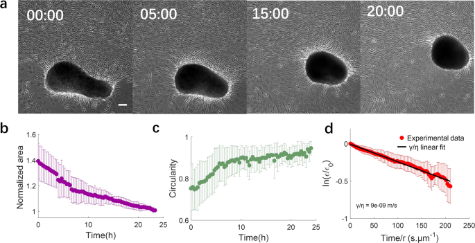
a Phase contrast images of a SMC cluster at different times showing progressive rounding. Times are in hours. Scale bar: 100 μm. b Time evolution of normalized cluster projected area. c Time evolution of cluster circularity defined as 4πA/P2, where A is cluster area and P is cluster perimeter. d Normalized cluster/spheroid anisotropy, allowing determination of the value of the ratio of surface tension to viscosity (γ/η). γ/η ~10-8m/s. Equation is indicated in the text. b–d Mean ± SD, N = 7.
A fit of Eq. (3) to the experimental data is shown in Fig. 3d, yielding \(\frac{\gamma }{\eta }\approx {10}^{-8}\) m/s, comparable to that reported for the rounding up of cellular aggregates of other cell types31. Once clusters round up, they stabilize in size and shape (Supplementary Fig. S6, Supplementary Note 4) unless they fuse with other clusters.
Cluster fusion
The interaction of two clusters that are sufficiently close to one another often leads to fusion (Fig. 4a). The fused cluster subsequently goes through the “rounding-up” and “stabilization” steps described above for single clusters.
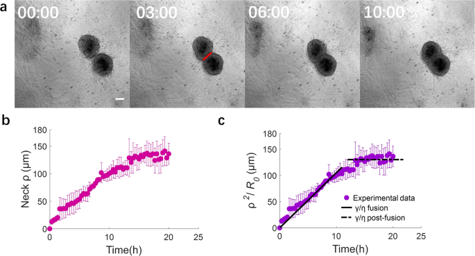
a Phase contrast images of two fusing SMC clusters at different times. Times are in hours. Red line: 2ρ, where ρ is the “neck” radius. Scale bar: 100 μm. b Time evolution of “neck” radius ρ for the fusion of pairs of clusters having approximately the same size (diameter ~200 μm). c Time evolution of the normalized neck radius. During fusion, γ/η = 2.9 × 10⁻⁹m/s. The “neck” radius stabilizes at the value of the cluster radius (~130 μm). Equation for γ/η is indicated in the text. Panels b and c: mean ± SD, N = 3).
Cellular spheroid coalescence has been described by analogy with the fusion of two viscous liquid drops33,34. Recent developments have investigated the dynamics of spheroid fusion and how these dynamics are affected by cell proliferation35 as well as by cell migration and the presence of ECM36. To analyze the fusion process, we quantify the evolution of the “neck” radius ρ, i.e., the radius of the contact region between two adjacent clusters as seen in projection on the experimental images. The observed neck evolution is reasonably fitted by the classic viscous sintering theory of Frenkel37,which has been widely used to describe cell aggregate fusion:33,38,39,40
$$\frac{{\rho }^{2}}{{R}_{0}}=\frac{\gamma }{\eta } * t$$
(4)
Here, \({R}_{0}={{{{{{\rm{sqrt}}}}}}}\left(\frac{{A}_{1}+{A}_{2}}{2* \pi }\right)\), with A1 and A2 the initial cluster areas, γ/η is the ratio of surface tension to viscosity, and t is the elapsed time since the beginning of the fusion process (Fig. 4b, c). We note that even if the cluster behaves as a viscoelastic material, the fusion dynamics at times longer than the viscoelastic time (minutes to hours) remain appropriately described by the viscous sintering model41,42. By fitting Eq. (4) to the experimental observations of aggregate fusion, we obtain a value of γ/η of the order of 2.9 ×10⁻⁹ m/s. Taking into account possible scaling factors that arise from our simplified geometrical treatment of the problem, this value of γ/η appears consistent with that obtained for the rounding-up process. Our findings thus suggest that both the “rounding-up” and “fusion” phenomena are governed by the same physics of an effective surface tension driving the morphological change, whose speed of evolution is limited by viscous dissipation. Interestingly, the apparent capillary velocity γ/η for fusion is one order of magnitude smaller than that of rounding-up. We attribute this difference to the presence of ECM especially at the cluster periphery, which slows down the fusion process (Supplementary Fig. S1b, c). This observation is consistent with previous reports of a role for the ECM in cell spheroid fusion dynamics36.
After stabilization of the fused cluster, we observe a post-fusion rounding-up process (Supplementary Movie 9). We quantify the post-fusion rounding-up in the same way as done for the rounding phase (Supplementary Fig. S7). We quantify the γ/η, the ratio of surface tension to the viscous dissipation, as well as the normalized projected area and the circularity for the fused clusters to analyze the post-fusion rounding-up dynamics. The post-fusion cluster rounded up within 16 h (Supplementary Fig. S7a). The projected normalized area decreases by approximately 20% (Supplementary Fig. S7b), and the circularity increases from 0.85 to 1 (Supplementary Fig. S7c). A linear fit to the experimental data yields \(\frac{\gamma }{\eta }\approx {10}^{-8}\) m/s (Supplementary Fig. S7d), which is of the same order of magnitude as the ratio of the normal rounding-up cases. These results demonstrate that the initially ellipsoidal fused cluster exhibits a rounding-up speed that is similar to that of individual clusters.
Prerequisite conditions for SMC cluster formation
SMC cluster formation as detailed above requires two prerequisite conditions: a sufficiently high cell density and sufficient levels of SMC contractility. The role of each of these two conditions is characterized next.
SMC density determines both the dynamics of cluster formation and the pre-cluster organization of SMC sheets necessary for initiating a cluster. We investigated the dynamics of cluster formation for the three different cell seeding densities tested (40,000, 80,000, and 160,000 cells/cm2) (Supplementary Fig. S8). We divide the clusters into two types (Supplementary Fig. S9): “developed clusters”, which have a clear and complete contour, and “developing clusters”, which have a partially developed contour. Not surprisingly, cluster formation occurs most rapidly at the highest cell seeding density for both types of clusters (Fig. 5a, b and Supplementary Fig. S8b). Furthermore, cluster formation at the lower seeding densities occurs only after a delay, suggesting that a critical cell density needs to be attained via cell proliferation for cluster formation to initiate. For both types of clusters, the number of clusters increases for several days until it reaches a maximum and then decreases before ultimately stabilizing at a plateau. For developing clusters, the increase is due to cluster formation because of cell proliferation, whereas the decrease corresponds to developing clusters maturing into developed clusters. For developed clusters, the increase is driven by the maturing developing clusters, while the decrease is due to cluster fusion once cluster density becomes sufficiently high for neighboring clusters to interact. The time evolution of the total number of clusters (i.e. developing and developed) exhibits similar overall behavior (Fig. 5c) once a shift of 3 days has been introduced for the low and medium seeding densities, so that t = 0 for all experiments is the time when cluster formation starts. With this shift, all experimental curves are approximately similar. This master curve first rapidly increases to reach a maximum, and then decreases to finally stabilize at a plateau.

a Time evolution of the number of developed clusters for the different cell seeding densities. The maximum number of developed clusters is reached at days 14, 9 and 4 for the low (LD), medium (MD), and high (HD) seeding densities, respectively. b Time evolution of the number of developing clusters for the different cell seeding densities. The maximum number of developing clusters is reached at days 6, 5 and 2 for the low (LD), medium (MD), and high (HD) seeding densities, respectively. a, b Mean ± SEM, N = 3. c Time evolution of total number of clusters (sum of developed and developing clusters) and physical model fit. Three experiments for each density are shown.
The master curve in Fig. 5c can be described by the following population dynamics differential equation:
$$\frac{{{{{{\rm{d}}}}}}N}{{{{{{\rm{d}}}}}}t}={p}_{1}-\alpha \left(t\right){p}_{2}N,$$
(5)
where N is the total number of clusters at time t, p1 is the rate of cluster formation, and p2 the rate of (relative) cluster number reduction, mainly arising from cluster fusion. The time-dependent parameter α(t) is introduced to account for a reduced rate of cluster number at short time, due to the time required for clusters to meet each other and fuse. We assume a linear increase of the dissociation rate over time, α(t) = min(t /ts,1), with ts being a certain stabilization time. The solution to this differential equation agrees closely with the experimentally observed shape. Figure 5c shows a comparison between the computational fit and the experimental data with fitted model parameter values of p1 = 50 clusters/day, p2 = 1.5 day-1 and ts = 8 days.
It would be instructive to characterize the organization of our SMC layers prior to cluster formation for the different cell densities. To this end, we quantify the extent of actin stress fiber alignment by computing the scalar order parameter Q for non-polar particles43 (Supplementary Fig. S10):
$$Q=\sqrt{{ < \cos 2\theta > }^{2}+{ < \sin 2\theta > }^{2}}$$
(6)
where \(\theta\) is the angle between the stress fiber direction and a reference direction (the horizontal direction in this case). Q ranges from 0 for a completely disordered case to 1 for a perfect nematic order where all stress fibers are aligned in the same direction. At low cell density, SMCs exhibit a wide range of orientations (Figs. 6a, 6c i) as indicated by the small value of Q = 0.18 ± 0.07 (Fig. 6b). At medium density, SMCs become confluent and coordinate with local alignment of stress fibers (Figs. 6a, 6c i), leading to considerably increased order (Q = 0.51 ± 0.16 (Fig. 6b)). At high density, SMCs rapidly form multiple layers (Figs. 6a, 6c ii), typically three (Supplementary Fig. S10), prior to cluster formation, and actin stress fibers within each layer are highly aligned (Supplementary Fig. S10b), with an order parameter approximately equal to unity (Q = 0.87 ± 0.13 (Fig. 6b)). These findings are consistent with previous studies43,44,45.
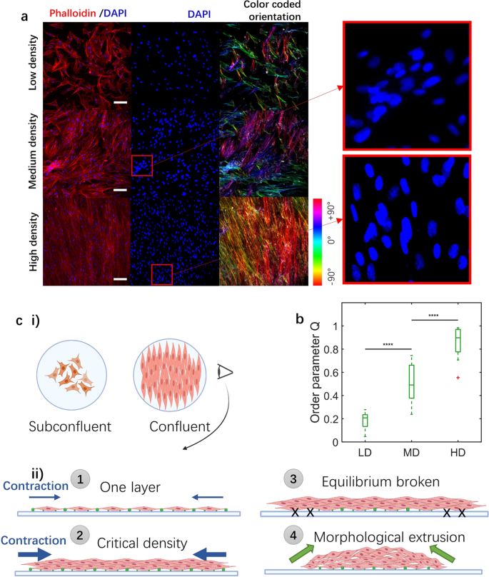
a Immunostaining images of samples with different seeding densities 24 h post-seeding. DAPI (blue) shows SMC nuclei, while phalloidin (red) shows F-actin. Nuclear overlap in some regions (see insets) demonstrates that cells begin to form local multilayer zones at the medium density. Scale bars: 100 μm. b Order parameter values for the low (LD), medium (MD), and high density (HD) cases. P value is calculated using a one-way ANOVA, ****p ≤ 0.0001, NLD = NMD = NHD = 15. Error bars represent standard deviations. c Schematic of density- and contraction-induced cluster formation mechanism. (i) Subconfluent field represents low density samples. Confluent field represents medium density samples. (ii) Schematic side view of morphological evolution with different seeding density. \(1\), One confluent layer of SMCs, \(2\) three to four layers (critical density) of SMCs, \(3\) Contraction force overcomes cell-substrate adhesions. \(4\) Morphological extrusion due to cell contraction and subsequent detachment from the substrate. Blue arrows represent contraction force of SMC layer. Multilayers have higher contraction force. Green dots represent cell-substrate adhesion.
Our results indicate that SMC cluster formation only initiates once a critical cell density is attained and the cells have formed several layers. However, cell density per se is not sufficient to initiate cluster formation. The additional required component is sufficiently elevated cell contractility in order to overcome cell-substrate adhesion as depicted schematically in Fig. 6c. Such force disequilibrium would lead to the tearing-off of the SMC cell sheet from the substrate. In support of this model, SMC contractility inhibition using blebbistatin (5 \({{{{{\rm{\mu }}}}}}\)M) significantly slows down cell detachment from the substrate (\(\sim\)30% decrease in detached area at day 3) and delays the formation of clusters (Supplementary Fig. S11a), A higher dose of blebbistatin (10 µM) completely inhibits cluster formation at day 2, and at day 3, the cell detached area is more than 20 times smaller than in untreated controls, confirming the important role that SMC contractility plays in cluster formation. We note that we attempted to probe the effects of even higher doses of blebbistatin (15 and 20 µM) on cluster formation; however, those doses led to detachment of the entire cell sheet, presumably due to the fact that high blebbistatin concentrations compromise the strength of cell adhesion to the substrate.
As an additional test, we investigated the dynamics of SMC cluster formation when the cells were cultured on very soft gels (Young’s modulus of ~2 kPa) on which their ability to generate large contractile forces is greatly diminished. The results demonstrated that when plated at the same seeding density, cluster formation on the soft gel required 3 days longer than on plastic (Young’s modulus ~2.7 GPa). Applying the model described in the “Rounding-up” section for the dynamics of cluster formation yields a value of γ/η that is 3 to 4 times smaller for the soft gel than for plastic (Supplementary Fig. S11b), consistent with a slower rate of cluster formation. These findings are consistent with the central role for contractility as the driving force for SMC cluster formation.
[ad_2]
Source link
